Post No 1 - British Bike Build

NORVIN BIKE BUILD BLOG
by
Neil Foreman
of
Neil Foreman
of
CAR BUILDER SOLUTIONS
my email: neil@cbsonline.co.uk

The ten posts in this Blog are the story of my first bike-build for forty five years - the NORVIN pictured below. There are more pictures of the finished machine at the end of the final post. Thanks for reading. To read the other posts click on the 'home' link at the bottom of this post.

The first few lines here are just an introduction about me and my background
Please feel free to skip straight to the meaty stuff below.
Please feel free to skip straight to the meaty stuff below.
I think I was about seven years old when my Mum and Dad bought me a 'Bayko Building Set' set for Christmas. My friends had plastic 'Lego' type blocks but the Bayko set had steel rods and proper doors, windows, bricks and tiles. I loved it - and so began a lifetime of making things. I soon discovered my Dad's Size 10 Meccano Set in his old bedroom at my Grandad's house and I began messing with nuts and bolts and electric motors.


Then in my early teens Slot Cars filled the school holidays. Riko kits offered a wonderful opportunity to upgrade from the standard, boxed Scalextric cars to ones that you build and paint yourself. I still have them all now and I'm looking forward to playing with them again with my Grandchildren, Matilda and Isaac.

At sixteen I started an Engineering apprenticeship with Elliott Automation in Rochester - soon to become Marconi then British Aerospace. I was taught by the very best engineers in the world how to saw, file and machine metal and how to assemble parts and systems for Aircraft such as Hercules, Concord, Nimrod, Jaguar.
My first transport to and from work at sixteen was my Mum's Honda 50 Scooterette. I ploughed through feet of snow over the North Downs that winter in just a trenchcoat, my Dad's old RAF boots, an open-face helmet with goggles and a silk scarf. My first real bike was a 250cc AJS bought from a friend for £40. There followed a Triumph Tiger 90, a Matchless 500 single Trials Bike and a Bonneville.

In the second year of my apprenticeship I built my first bike - a 'NORBSA' with a 650cc BSA engine in a Norton Featherbed frame. I clearly remember paying £40 for a BSA Super Rocket in bits. I had the engine and my pal, Steve took the frame to build a TriBsa. I can't recall how much I paid for the Norton frame but it couldn't have been much. I was an apprentice earning only £6 a week plus a few quid from my first working band. I remember fabricating a cylindrical oil tank in the Marconi machine shop. One of my apprentice mates' Dad was a welder and he 'Tigged' it up for me between Concord instrument cradles. I got a severe bollocking from the Flight Controls Division Foreman for putting my oily chain-cases into the Ultrasonic cleaner alongside a batch of Hercules altimeter parts. Ooops.
Sadly I can't remember much more about the bike except that I crashed it into an Austin A35 when a stupid old bitch driver pulled out in front of me looking the other way. The GRP tank was smashed and replaced with an aluminium one, the headstock was bent back and straightened by another friend who worked for Don Godden Engineering and the bent fork legs were replaced - all before the road-rash scabs had fallen off!!! It was on this bike that my mate Roger and me first did 100mph down Bluebell Hill with bobble hats on. I even rode it to Cornwall and back - with clip-ons. Jeezus !!
That bike probably cost me less than £100 - and here's the only picture I have of it. I eventually sold it to fund the next toy - a Berkeley T60, through a bike shop in Sittingbourne, for about £300. Similar bikes today sell for around £8,000.

From Marconi I joined a young company called Lynx Engineering building and restoring D and C Type Jaguars and other exotic Classic Racing Cars.
Fast forward about twenty years and I formed 'N F Auto Development' and began manufacturing the 'Foreman Mk4' - a replica of Ferrari's classic 'P4' LeMans Sport Prototype racing car.


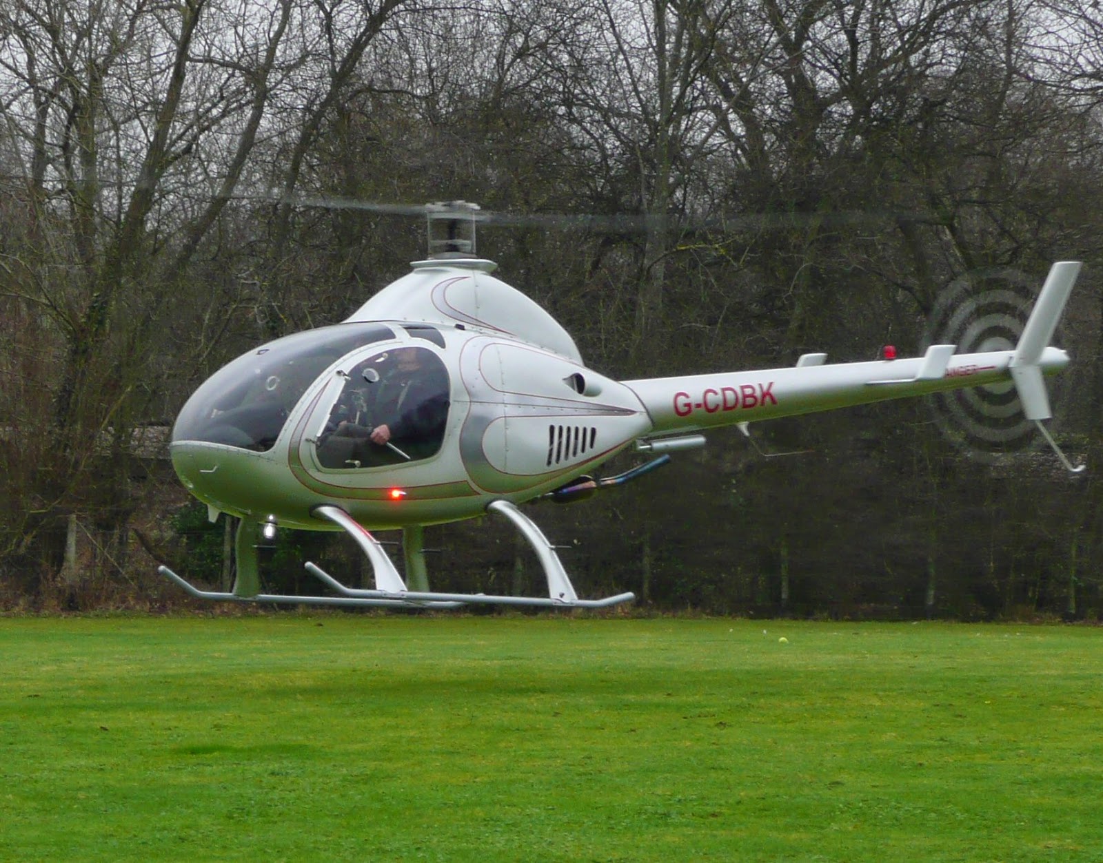
Fifty Mk4's later, in 2004, at age 50, I built and learned to fly a two-seat Rotorway Helicopter.
It took me a year and about a thousand hours to build. I guess I was tougher then because my workshop wasn't very well insulated and I worked evenings and weekends through the long cold winter with only a smokey, Swedish Army, diesel fuelled, tent heater to keep the chill away. My old dog, Baz and Planet Rock on the radio kept me company every step of the way.
After the Rotorway build, my company Car Builder Solutions began to grow rapidly and 'Toy Time' became very elusive. My two other projects - a 1960 Berkeley T60 build (with a Honda CRX engine) and the final Foreman P4 build that we retained as a family heirloom when we sold the project to Dunlop, still sit firmly on the back burner but we still have a comprehensively equipped workshop with Grit and Bead Blasters, Mig and Tig Welder, Plasma Cutter, Lathes, Milling Machines, Fly-presses, Guillotines, Cut-off Saw, Bandsaw, Polishers, Drill-presses and pretty-much all the Air and Hand Tools we could possibly need.
Launching and growing 'Car Builder Solutions' and forming my Classic Rock Band, 'The fabulous Grandads' filled the following ten years until, for my 60th birthday, my Son, Matthew bought me a beautiful BSA Rocket Gold Star.

Soon the nostalgic urge to build another NORBSA began to nibble away at my 'semi-retirement'.
It didn't take long to discover the shockingly high price of Classic British Bikes and Parts for them.
I guess it's a factor of low interest rates for savers and so many people jumping on the Classic Bike bandwagon as a better investment prospect for their hard-earned dosh.
I've always have had an inherent desire to understand how things work - and if I didn't know, then I'd take it apart to find out. I can understand all of the mechanical and much of the electrical systems on my Helicopter and I can understand all of the mechanical and all of the electrical systems on a Chevy-engined P4, so the relative simplicity of the NORVIN should render the project stress-free and a delight to build. (see 'Famous Last Words !!)
So, the search was on for a Norton Frame and BSA 650cc engine - although the prospect of a 500 single engine did cross my mind. Two 'rolling' frame options appeared on ebay. One, a 1960 Wideline, had Bonneville forks and wheels, a Dresda swinging arm, Akront alloy rims, alloy tank and a few other tasty bits plus a V5 registration document. The other was an unregistered, unfinished bike with a slimline frame and some other nice bits. But it also had a 'rebuilt' BSA B33 engine and BSA gearbox fitted. However, the owner kindly admitted that he had run the engine for ten minutes with no oil flow before discovering several stripped teeth on the oil pump! Both owners were asking £3500.
My Son, Matt eventually came to a deal with the Wideline owner for £3k and we collected it in the van. Here is is exactly as I bought it.

Finding an engine wasn't quite as easy. Again, demand has pushed prices up well beyond what I had expected - so a BSA 650cc engine in a cardboard a box - no guarantee that everything is there or working, no carb, no magneto or dynamo and no gearbox would have a price tag of £1000.

Is this worth £1000 ??
I was really in no rush - scouring the internet every day waiting for a decent engine to come along, when I happened to spot a Vincent Comet engine for sale in Austria. With a Buy-It-Now price of almost £4000 I dismissed it instantly - until, the next day, there also appeared on Ebay a Comet-engined NORVIN at £22,000 !!! Bloody hell!! OK, it would be an expensive bike to build but I reckoned that it's final value, if I were ever to sell it, would be proportional.
From the pictures, the Austrian engine looked reasonably OK and in good external condition, No visible damage, broken bits or badly rounded nuts, so I called the seller in Austria at about 8 O'clock on Sunday evening - not really expecting an answer. I ended up chatting to an Englishman, Mark Upham, the main man behind the resurrection of the wonderful Brough Superior. He knew of me and the Foreman P4's and we talked for ages, eventually striking a deal on the Comet engine.
I wondered if I could use a BSA gearbox that I'd bought as as spare for my Rocket. Mark told me it had been done before and he had a clutch kit exactly right for the conversion. So I bought that too along with a new primary sprocket and shock absorber assembly.
A week later it all arrived - well packed in a big carton and it looked quite clean, tidy and un-messed-around-with. The crank turned freely and there was compression but it had obviously been taken apart at some time. The ebay listing had included the phrase '.... for rebuild or parts' so stripping it right down for a check over was the obvious first step.
Once upon a time I'd tear into a project and complete it without coming up for air. But these days I seem to spend more and more time thinking, planning and wondering how to do it. I know that I'm losing my edge but it was Matthew's birthday gift (the BSA) that fired-up my Mojo again and sparked the NORVIN project. Well, it's manageable, doesn't take up much space and my workshop is now better insulated so, I hope I can see this one through to the end.

Next - the search for information. How did we ever manage projects like this without the Internet? Of course, we had no choice - we just got on with it. Information came from friends, shops, manuals and from making mistakes - learning the hard way. These days, a Google search will find you an answer to pretty-much any question. Manuals, Drawings and Parts Lists can be downloaded, printed and in your hands in seconds. Forums, Owners Clubs and Blogs like this one are invaluable sources of accurate and directly relevant facts and information. Within days I had a file of printed Handbooks, Service and Rebuild Manuals, Parts Lists and Drawings on the Comet Engine, Norton frame and Bonneville parts.
1st March 2015
So, back to the Blog. It's been about four months since I wrote the previous paragraph and I delivered the engine - partially stripped to Conway Engineering, a local Vincent specialist. I'd removed the head and barrel to discover no major, internal, disaster areas. One of the valve seats had, at one time, come loose and had been tightened up with a ring of centre-punch 'dings' all around it's edge. There were a few scratches on the bore and the exhaust flange thread was partially stripped. 'Steve' at Conway replaced both valve seats and machined the exhaust outlet to accept a new, threaded brass insert. He recommended a new liner and standard piston as the existing piston was not a Vincent one. I'm still waiting for the bottom end to be stripped and inspected. Bit disappointed - I was told it would be done after Christmas. He didn't say which Christmas though. No one seems to do what they say they're gonna do these days - or has it never been any different?
Over the years I've learned never to believe that so-called 'rebuilt or reconditioned' parts actually have been rebuilt or reconditioned - at least, not to a standard that's acceptable to me. The rolling frame was supposedly built-up ready to accept a Triumph engine but had obviously been standing in damp conditions for a few years and most things that I looked at closely needed attention. So, I've been dismantling, prepping and rebuilding it - in no particular order. I decided not to completely strip and repaint the main frame at this stage because I can't be sure which brackets I need to add or remove for the NORVIN conversion. but to just to 'touch up' the dodgy bits, build and test the bike then strip it again once it has been fully sorted, for a proper repaint.
So, in no particular order, here are some pics I've taken along the way with a few words on each.
This is the underside of the bolt-in, frame cross piece fitted just above the swinging arm. The hole here was made by the badly-adjusted rear chain flapping up and down, wearing it's way through the steel tube. I machined the hole clean and square and welded in a new, half-round section of tube.


I made a stainless cup to cover the speedo drive on the rear hub.

I bought these stainless 'Vincent' handlebars from a reputable supplier only to find that the bends were not central but offset to one side by about 30mm. They replaced them no problem.


I used a spare pair of NORBSA mounts to hold the BSA gearbox roughly in position. The ali rear sprocket and brake plate have been polished and the rear wheel mounted on a new stainless spindle with all new stainless spacers and washers. What's more - it looks like the alignment will be fine.


The aluminium front brake plate needed some TLC. Complete strip down and dress-up with a Scotchbrite disc on an angle grinder, then polished.


Front shoes look tatty but that's just the unusual paint finish. They're pretty-much brand new.

I love POR15's 'Blackcote' aerosol paint. It's expensive - about £25 for one can but it's a really tough, isocyanate-based paint that cures when exposed to moisture. These parts have been stripped, masked and blasted then given a thorough wash with thinners before four or five coats of Blackcote.


Here's a makeshift spring compressor for the rear shocks. Just a luggage tie and a screwdriver. Keep twisting like a tourniquet. Simples.

The KONI shocks that came with the frame were a bit tatty but mechanically fine. I replaced the bushes with polyurethane ones and made new stainless sleeves for the different bolt sizes top and bottom. A quick polish for the upper and lower aluminium spring seats made 'em better than new.


One fork leg had a leak at the bottom and was almost dry of oil. I stripped them completely and dressed the ali legs Scotchbrite discs. There was an amazing amount of crud collected in the bottom of the legs which took a long brush and several washes with thinners to clean out. No wonder there was a leak. New seals all-round.


Everything fork-wise is in very good nick for 1971 vintage - can't have had much use.

Yup - been polishing - and that's with a mask, goggles and hood !!!

These nice die-cast headlamp brackets are readily available but they're universal and come with black plastic spacers to adapt them to the diameter of the fork legs. I turned some aluminium sleeves with a flange at one end......


Better than the placcy ones
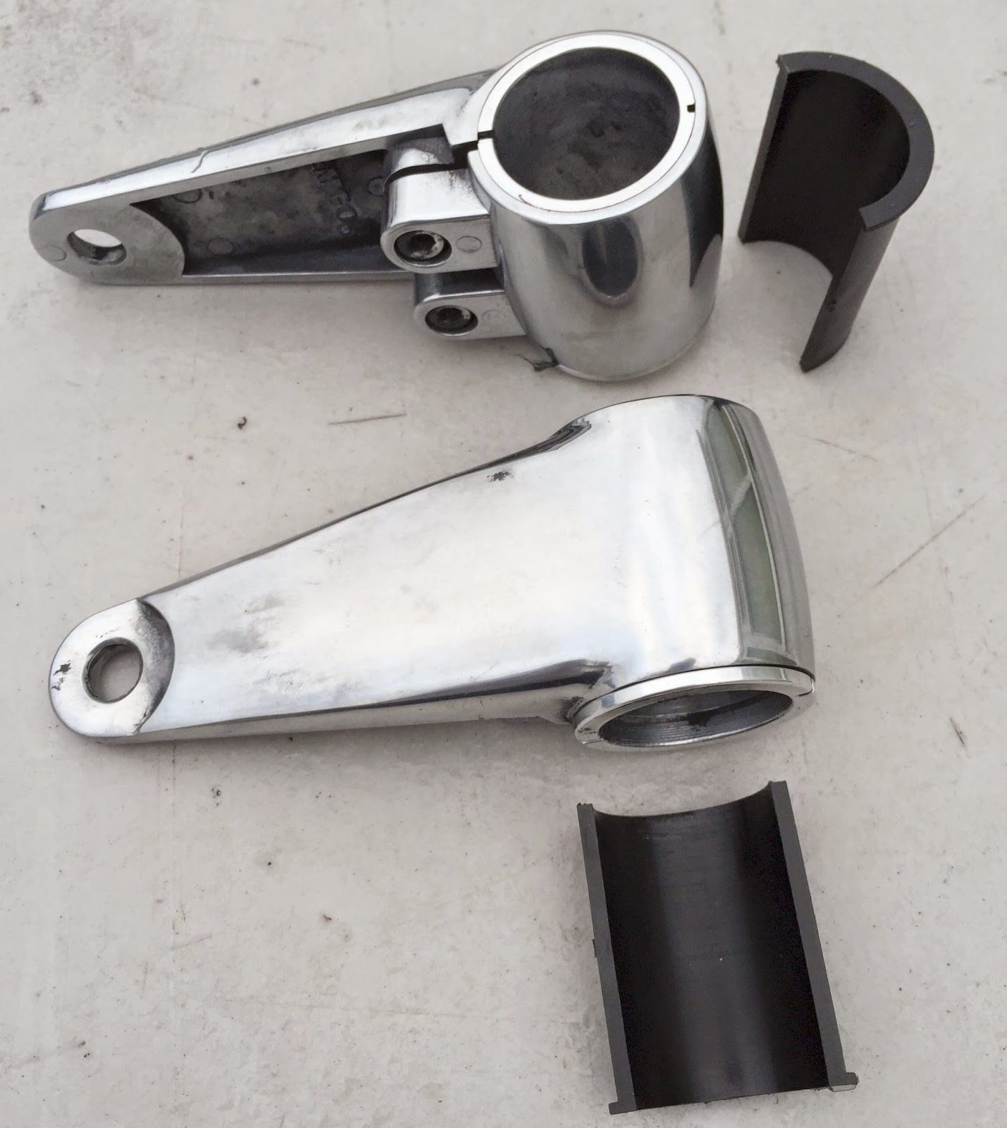

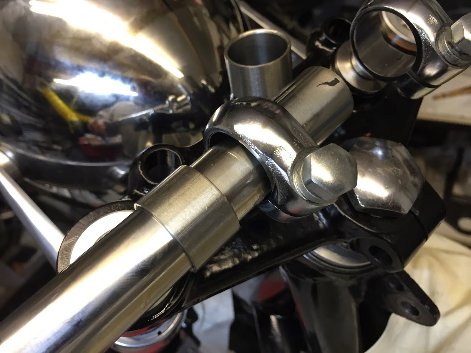
The stainless Vincent handlebars are 7/8" diameter and the Bonneville handlebar clamps are 1" so I made some stainless bushes to match them and cut the bushes into two so they'll clamp around the bars.
I couldn't find a supplier of stainless 7" motorcycle headlamp bowls so I used a car one from our CBS stock. I removed the post mount parts and drilled mounting holes in the sides. I turned some aluminium spacers and cut them in half at an angle to match the curvature of the bowl. Ideally the spacers should be concave and convex to perfectly match the inside and outside curve of the bowl. But they're only 1" diameter so I reckon they'll just flatten the curve of the bowl between them as they're tightened up.


Here's our little blasting cabinet. This one has fine grit for light cleaning before paint. We also have a much bigger one with coarse grit in it.

I brazed two little brackets to the frame cross-member just behind the tank to take the tank strap over-centre fastener.

Gotta workout a plan to get the engine and gearbox sitting perfectly in position before I decide how to make the mounts.
First draft - I cut a piece of 10mm ply, screwed to pieces of batten to it to locate between the bottom frame rails. I then cut a piece of 3mm ali, folded it into a shallow 'V' - only a couple of degrees to match the angle of the underside of the crank-cases, and trimmed it to sit flush with the top of the bottom frame rails. Hmmmm ....

OK so the engine's sitting there but there's no way to accurately adjust it's position. Little stacks of aluminium wedged under each corner ain't good enough. Rethink.

Meanwhile, I had to perform some drastic surgery on the crankcase that could bring tears to the eyes of a Vincent purist. There's a casting web with extended boss on the bottom of the left hand crank case. It's obviously there as an additional mount for the Vincent gearbox and primary cases. I don't plan on using either so it's in the way and needs to come off. I supported the main weight of the engine on a table and clamped the crankcase to the mill bed - flat and level.


While I wait for some Vincent parts to arrive I'm replacing all possible nuts and bolts with Stainless ones. Where they are 'on show' I'm skimming off the stamping and polishing them. Nothing like a bit of Blingy Bullshit


This years birthday prezzie from my Son Matthew. This superb (German) MOTOGADGET instrument. It's about as high tech and modern inside as they come with discrete digital display of Speed, Oil Temp, Oil Pressure, etc. It can be programmed to display as many of the functions as you like topped off with a classic analogue Rev Counter dial. I made a simple stainless mounting plate, silver-soldered to a spigot that drops into a spare boss on the top yoke and secured with a grub screw

Plan 2 for the engine location method. I cut a foot square piece of 18mm ply and clamped it to the bottom frame rails with the trimmed 3mm ali plate. I inserted two, 300mm long pieces of studding through the front and rear crankcase mounting holes and made up four adjustable-length support pillars from 25mm diameter aluminium bar and some 50mm pieces of M10 studding for each end of each mounting stud. Unscrewing or screwing together each pillar assembly, raises or lowers that corner of the engine allowing me to adjust it's horizontal and vertical position very accurately. Here I'm using a toolmakers spirit level to set the vertical plane.

Fortunately, with the gearbox mounted centrally in the frame, it's drive sprocket sits perfectly in-line with the rear wheel sprocket leaving only it's up/down and forward/backward positions to be determined. I've fitted a standard Vincent Comet exhaust pipe so this will help with the clearance of the frame down-tubes and the forward/backward position of the engine. I have decided to run the primary chain dry so I'm not committed to use the Vincent primary cases. I'll make my own case around the final position of the engine and box.

Four new engine mount brackets are brazed to the frame, at the front and rear of the crankcase on either side. One small alloy plate at the front is way more elegant than other huge plates I've seen that pick up on the standard Norton front frame mounts.

I made a head steady mount from 5mm steel that links the head studs to an unused fuel tank mount on the frame.

Here we go then. First step - roughly-shaped card templates for the rear engine/gearbox mounts. Holding the card in place you can press around the holes to make an impression on the card and get pretty accurate positioning. Positioning the gearbox in all three dimensions is critical at this stage. Fore and Aft to allow fitting and adjustment of the primary chain. Up and Down to ensure optimum tension on the rear chain when a rider is sitting on the bike. And Left and Right for primary and rear chain alignment

I always use a step-drill for making the holes in sheet and plates. The 3mm first stage allows you to 'pull' the hole centre like a centre-dril for spot-on positioning. The final hole is always perfectly round, clean and accurate. If you're careful when you reach the correct size step you can even de-burr the hole by just touching the next step.

The first mock-ups are in 3mm aluminium. There's a mixture of 5/16", 3/8" and 7/16" mounting holes. This is one of those on-off-on-off-on-off jobs which seems more instinctive than scientific. What I'm after here is minimum bulk with elegance and adequate strength to do the job. I feel myself getting happier as the shape is refined. Author, Robert Pirsig, sums it up in this line from his book ' Zen and The Art of Motorcycle Maintenance' .....
'The material and the Craftsman's thoughts change together in a progression of smooth, even changes until his mind is at rest at the exact instant the material is right.'

It's more trial and error - on- off-on-off - trimming and refining the shape to maintain clearance around the casings whilst keeping maximum strength. You can see here the crankshaft oil seal mod and it's carrier plate - as yet unsecured. This is to prevent oil weeping through the crank bearing into the primary chain case - because I'll be running it dry.

Finally time to transfer the profile to 1/4" aluminium plate for the real mounts. I drew around the 3mm templates with a 'Sharpee' which makes a 2mm thick line. I cut the 1/4" plate with my Makita battery Jigsaw and plenty of WD40 lubricant right along the middle of the Sharpee line.
I made the left hand mount in two pieces with an overlap. This 'stagger' moves the plate inboard to give a little more clearance for the gearbox final drive sprocket and the rear chain. The two parts are dowelled together here but I will add countersunk bolts later. The elongated hole is for adjustment of the primary chain tension.

Left and right plates are slightly different shapes but there are some common edges. So I bolted them together and cleaned-up the straight runs on my mill.


OK - all back together for an alignment check. I tied the bike to the lift with rachet straps and used a piece of heavy aluminium angle as a datum to adjust the rear wheel tracking parallel to the front wheel. I've temporarily fitted the primary chain which is a continuous, 66 link 'O' Ring chain. It should be reliable and will need no lubrication in the chaincase.

Plates all fettled and polished.

Onto the gearbox for a while. I bought the Pre-unit, BSA A10 box from ebay. It looked pretty good in the pictures which I confirmed with a quick inspection. But pretty good isn't good enough. Better sort it out properly. I made a stainless steel replacement inspection cover. And new gaskets.


I removed the worm-driven speedo drive ('cos I have a satellite speedo transducer for the Motogauge instrument.) This left a 5/8" hole through the gearbox casing. I turned up two tapered plugs just over 5/8" diameter and pulled them together on both ends of the hole with a long M6 bolt. Sealed.

I found this 1/4" BSP magnetic drain plug from RS Components.

Once again, the engine is set up on the milling machine - blocked and clamped level - all just to drill and tap the three holes for securing the crank seal carrier plate.

And here it is - all done. (It's to prevent crankcase oil from seeping through the main bearing into the primary chaincase, which I'm running dry.)

Here I've removed the two original Norton front engine mounting brackets from the frame and I've completed the brazing of the four new mounting plates on the bottom frame rails.
At this stage I won't be stripping and repainting the whole frame - I'll just prep and repaint the areas I've worked on then, when the bike has be assembled and shook-down for a season, I'll strip it and paint the frame properly.

So, for now, it's just prep and paint for the down tubes / bottom frame rails. Just to stick with the top quality job, I've used her ladyship's puresilk curtain liners for masking sheets.

POR15's Blackcote Aerosol again (available from CBS). This is amazing stuff but you have to be careful building up coats slowly or it'll run. Warmer is better. You can rub down with 400 grit W&D after a day and put a few more coats on.

A tidy bench is a happy bench.

I checked out the gearbox and replaced a few parts including the seals. And I added this one - a clever mod. from SRM which cures the notorious BSA oil leak from around the input shaft.

The gearbox casing is in pretty good nick but I gave it a bling-up with this little stainless steel wire brush (available from CBS) and some thinners.

Back on the mounts again for a final alignment check. The easiest and most reliable datum to use for aligning the engine and transmission is the swinging arm shaft. Here I've replaced the shaft with a longer, 5/8" diameter steel bar and I've clamped a 'Vee' block around the end of it. I can now check the vertical and horizontal plumb with my toolmakers spirit level and here I've clamped a straight piece of angle to the Vee block and I'm checking that the engine casing is square to the shaft. Steel rules are pretty accurate to within a quarter of a millimetre or less but a digital caliper will get it closer. Ideally, the crankshaft and the swinging arm shaft should be parallel.

Here's the gearbox - all blinged-up. New kickstart quadrant and all stainless nuts, screws, studs and plugs.

posted by Neil Foreman @ 13:35
![]()

<< Home